Get a quote

Flexible PCB

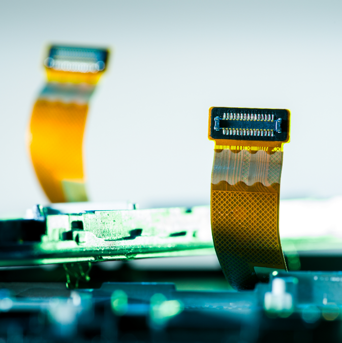
Flexible printed circuit boards get the name from the ability to be bent in a working application. This is called dynamic flex. Other flexible design is Intended to be folded to be able to fit a very narrow space in the final assembly.

What is flexible PCB?

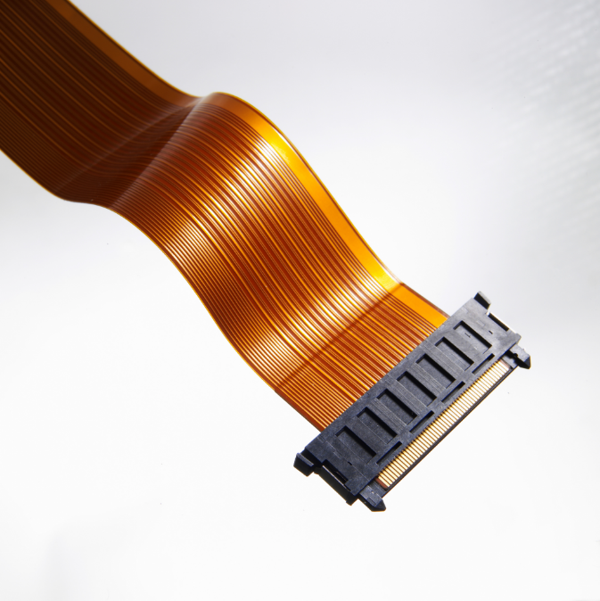
Flexible printed circuit boards (also variously referred to as flex circuits, flexible printed circuit boards, flex print, or Flexi-circuits) are electronic and interconnection family members. They consist of a thin insulating polyimide (PI) film, having conductive circuit patterns affixed thereto and typically supplied with a thin polyimide coating to protect the conductor circuits.

Flex PCBs provide more excellent options for designers and engineers when assembling electronic circuits. The flexibility opens them up to use in a wide range of applications.

The technology has been used for interconnecting electronic devices since the 1950s in one form or another. It is now one of the most important interconnection technologies in use to manufacture many of today’s most advanced electronic products.

More historical reading about Flex can be found in our blog post here.

What are the advantages of flexible PCBs?

  • Conserving space. Flexible PCB boards take up around 10% of the space and weight of standard circuit board assemblies, allowing for more installation, tighter bends, and packaging flexibility.
  • Increased Capabilities. The flexible printed circuit boards can be used with almost any connector or component, and they function well with ZIP connectors. They also perform exceptionally well at severe temperatures and have superior radiation and chemical resistance.
  • Have higher signal integrity and lower Dk (Epsilon) than ordinary glass-fibre laminates. Can with advantage be impedance controlled.
  • Heat endurance and durability. Flexible PCBs are frequently built of polyimide or a comparable polymer. Most rigid circuit board materials do not disperse heat as well as this material. As a result, flexible circuits can be used in difficult areas where a rigid circuit board’s performance would be compromised by heat. Flexible printed circuit boards may be built to resist high temperatures ranging from -200° C to 400° C, which is why they are so popular in the oil and gas industry for borehole measurements.

Different types of Flexible PCBs

According to the IPC-6013 classification, there are 3 types of flexible constructions, depending on layer count and/or use of stiffener.

Type 1

  • One conductive copper layer bonded between two insulating polyimide layers
  • Single-sided access, dual-sided access, unsupported fingers
  • Stiffener materials: polyimide, FR4, stainless steel, aluminium

Type 2

  • Two conductive copper layers with an insulating polyimide between and external polyimide insultaing layers
  • Plated through-holes provide circuit connection between layers
  • Single-sided access, two-sided access, castelated holes
  • Stiffener materials: polyimide, FR4, stainless steel, aluminum

Type 3

  • Three or more flexible conductive layers with flexible insulating layers between each one and external polyimide insulating layers
  • Single-sided access, two-sided access, castelated holes
  • Stiffener materials: polyimide, FR4, stainless steel, aluminum.

Capabilities

Feature

Capability

Number of Layers

1-8 layer

Build Time

3-5 days

Polyimide base material

Polyimide, PET, polyester -Flex

FPC Thickness

0.08-0.4 mm

Min Track/Spacing

>=0.06 mm

Min Hole Size (diameter)

>=0.35 mm

Coverlay (Flex Part)

Yellow Coverlay, White Coverlay, Black Coverlay

Silkscreen Color

White, Black

Surface Finish

Immersion gold, OSP, Immersion silver, Immersioni Tin

Finished Copper

0.5-2oz

All you need to know about Flexible PCB

Flex

Flexible materials low weight, high insulation capacity, and stability under extreme temperatures and, not least, the ability to let the circuit to be bent must be the big advantage over rigid PCBs.
The rigid PCBs easier production and much lower material cost are crucial, what make rigid PCBs the first choice.

Its broadly the same way you design a rigid PCB, but with the big difference that you have to consider incorrect mirroring of folded contact ends. This can easily be avoided if you print your final design on a common paper printer for checking.
The other big difference is the unequal thickness of the PCB area that demand you to present a carefully made stackup drawing.

Mostly all flexible PCBs contains one or two layers of copper. Grand part are the one layer design, since a lot of flex-strips and flex-cables actually are flex PCBs. Multilayer ( 4 or more copper layers) can be seen, but since bend ability drops radically with 2 or more layers its quite unique.

The general part of the flexible designs is made of polyimide (PI) but are often referred to as Kapton, witch however are a famous brand owned by DuPont company.

The major reason for designing PCB in flexible material are the bending ability of the circuit. Eigther as a fixed bent mounting or as dynamic flexing design. Low weight and excellent possibility for miniaturization.

Flex PCB is the same as the ordinary PCB, but with the difference that the base material is flexible. This is to let the circuit be able to be bent during a lifetime or be installed in a static folded mode. There are many design rules to take into account when designing flex PCB.

Explore our other products

Standard PCB

Our definition of “Standard PCB” is a rigid glass-fibre board with one or more layers.

HDI PCB

High-dense-interconnect PCBs meet the demand for smaller PCB with more compact components by increasing wiring capabilities.

Rigid-Flex PCB

RIGID-FLEX PCB excels in overcoming space and weight constraints due to spatial degrees of freedom.

Metal Core PCB

A metal core printed circuit board uses metal as its base material to spread heat accumulated due to some electronic components operating on the board throughout the board.

High-Frequency PCB

High-frequency PCBs are often needed while developing high-frequency products, such as satellite systems, radio frequency, microwave, mobile telephone base stations, etc.

Solder Paste Stencils

Customized high-precision laser-cut solder paste stencils are used by the subcontractor assembly company to apply solder paste with high accuracy to all places that shall be soldered.

Prototypes & Pilot Runs

PCB prototyping can be the most important step during electronic development.

Learn more how we ensure quality of our products.

Learn more

Capabilities

Feature Capability
Number of Layers 1-8 layer
Build Time 3-5days
Polyimide base material Polyimide, PET, polyester -Flex
FPC Thickness 0.08-0.4mm
Min Track/Spacing >=0.06mm
Min Hole Size (diameter) >=0.35mm
Coverlay(Flex Part) Yellow Coverlay,White Coverlay,Black Coverlay
Silkscreen Color White,Black
Surface Finish Immersion gold,OSP,Immersion silver,Immersioni Tin
Finished Copper 0.5-2oz

Contact sales

Let’s get this conversation started. Tell us a bit about yourself, and your needs. We will get back to you within few hours.

Get a quotation

    We will get back to you within few hours