Get a quote

Metal Core PCB

Although the LED industry has grown fast in recent years, the issue of heat dissipation has confounded LED application and growth, particularly in the sector of lighting. The use of Metal Core PCB opens up a new way to effectively solve LED heat dissipation.

What is Metal Core PCB?

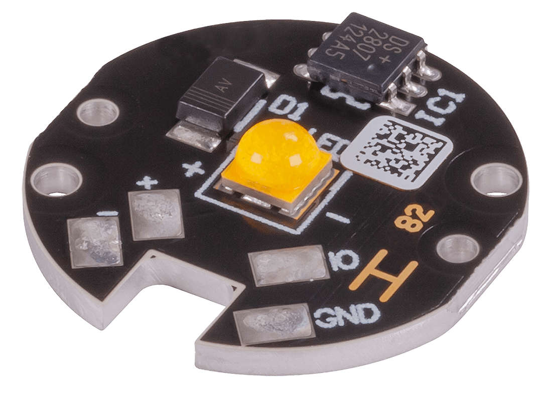
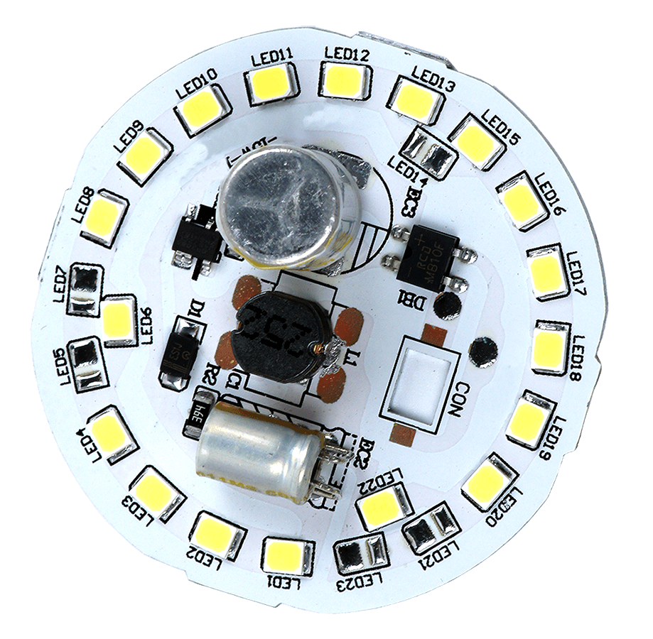
The metal core printed circuit board comprises a thermal insulating layer, a metal plate, and metal copper foil. It has high magnetic conductivity, great heat dissipation, high mechanical strength, and outstanding processing performance. There are aluminum, brass, and copper basis materials for metal core base materials. The aluminum substrate is a metal-based copper-wrapped plate with excellent heat transfer and dissipation properties.

A metal core PCB board uses metal as its base material rather than the standard FR4 to spread heat throughout the board. Heat accumulates because of some electronic components operating on the board. The metal aims to direct heat away from essential board components and onto less critical places.

What are the options for metal core PCBs?

Aluminum PCBs are ordered more often because the price of aluminium PCBs is much more economical; they are used for LED lighting, audio frequency apparatus, and electronic communication equipment. The base material consists of an aluminium core with a thin layer of insulation and a copper foil. Currently, Aluminum Backed PCB is regarded as the solution to high power and tight tolerance applications.

Aluminium delivers a product with strength and endurance – it is a durable foundation material that can help prevent accidental fracture during production, handling, and everyday use. Aluminium is non-toxic and recyclable, making it environmentally friendly. Because of its ease of assembly, aluminium manufacturing is also helpful to energy conservation. Using this metal by printed circuit board manufacturers helps to keep our planet healthy.


Copper and brass PCB boards feature better performance than aluminium but are heavier and involve a tough machining process. Large PCB cross-sections for high current loads are possible thanks to the thick copper, which also aids heat dissipation. Using this PCB technology, it is also possible to mix precise pattern structures on the outside layers with large copper layers in the inside.

Household appliances, high-tech items, military, medical, and other electronic devices employ thick copper PCB. The use of thick copper PCB extends the service life of the main component of electronic equipment products-circuit boards while also assisting in reducing electronic equipment size.

Specifications

Feature

Capability

Material

Chin-Shi, Chaoshun, Rogers, Berquist etc

Thermal conductivity

1.0 W/(m*k), 2.0 W/(m*k), >2.0 W/(m*k)

Min. Track / Spacing

4 mil

Min. Hole Size

0.8 mm

Base Material

Aluminum, FR4, Flex, Flex-rigid, HDI, Rogers, etc.

Board Thickness

0.4 - 3.2 mm

Surface Finishing

Immersion Gold, OSP, Hard Gold, Immersion Silver, Enepig

Finish Cooper

1-4 oz

Solder Mask

Green, Red, Yellow, Blue, White, Black, Purple, Matte Black, Matte Green

Silkscreen

White, Black

Via Process

Tenting Vias, Plugged Vias, Vias not covered

Testing

Fly Probe Testing (Free) and A.O.I. testing

Manufacturing time

2-3 days

Transport time

1-3 days

All you need to know about Metal Core PCB

Metal Core

The metal core substrate is manufactured with three different materials.
copper, isolation and the core (usually aluminum). The key function is the isolation layer, since there is a wide selection of different ability of the isolation layer to disperse heat.

The major advantage is the high ability to absorb heat that some components will create during runtime. LED armature and power supplies is a typical area of use. The mcPCB transfer heat 8 to 9 times faster than FR4 PCBs

The most common metal core PCB is a one conductive layer with a base laminate of solid aluminium (the core). The interconnection between is made of an electrical insulation that can disperse heat to the aluminium core.

A common PCB is made of glass-fibre epoxy and the mcPCB is made of metal.

Explore our other products

Standard PCB

Our definition of “Standard PCB” is a rigid glass-fibre board with one or more layers.

HDI PCB

High-dense-interconnect PCBs meet the demand for smaller PCB with more compact components by increasing wiring capabilities.

Flexible PCB

Flexible printed circuit boards get the name from the ability to be bent in a working application.

Rigid-Flex PCB

RIGID-FLEX PCB excels in overcoming space and weight constraints due to spatial degrees of freedom.

High-Frequency PCB

High-frequency PCBs are often needed while developing high-frequency products, such as satellite systems, radio frequency, microwave, mobile telephone base stations, etc.

Solder Paste Stencils

Customized high-precision laser-cut solder paste stencils are used by the subcontractor assembly company to apply solder paste with high accuracy to all places that shall be soldered.

Prototypes & Pilot Runs

PCB prototyping can be the most important step during electronic development.

Learn more how we ensure quality of our products.

Learn more

SPECIFICATIONS

Feature Capability
Material Chin-Shi, Chaoshun, Rogers, Berquist etc
Thermal conductivity 1.0 W/(m*k), 2.0 W/(m*k), >2.0 W/(m*k)
Min. Track / Spacing 4 mil
Min. Hole Size 0.8 mm
Base Material Aluminum, FR4, Flex, Flex-rigid, HDI, Rogers, etc.
Board Thickness 0.4 - 3.2 mm
Surface Finishing Immersion Gold, OSP, Hard Gold, Immersion Silver, Enepig
Finsih Cooper 1-4 oz
Solder Mask Green, Red, Yellow, Blue, White, Black, Purple, Matte Black, Matte Green
Silkscreen White, Black
Via Process Tenting Vias, Plugged Vias, Vias not covered
Testing Fly Probe Testing (Free) and A.O.I. testing
Manufacturing time 2-3 days
Transport time 1-3 days

Contact sales

Let’s get this conversation started. Tell us a bit about yourself, and your needs. We will get back to you within few hours.

Get a quotation

    We will get back to you within few hours